Unequaled work holding accuracy for grinding, balancing, inspection, boring, facing, reaming, drilling, turning, shaving, hobbing and honing.
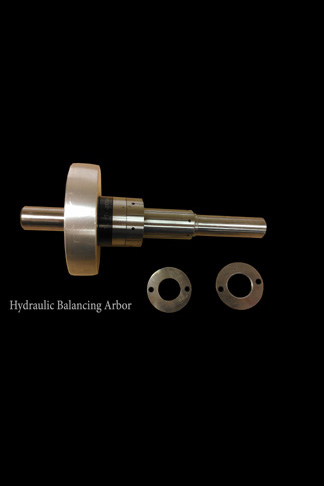
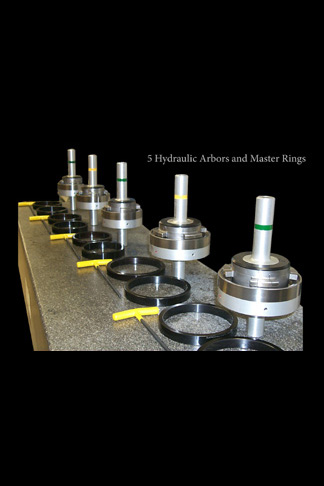
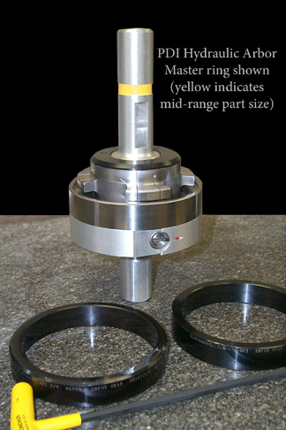
Grip arbors and chucks utilize a self-contained hydraulic system to expand or compress the sleeve within the gripping area to point within the elastic limits of the metal. The pressure is supplied through an internal piston assembly which can be actuated either manually or power assisted. The illustrations demonstrate a manual actuation to expand the arbor, or compress the chuck. Clockwise rotation of the actuator screw advances the piston which places the hydraulic system under great pressure. The chuck, Figure 1 – the compression area is limited by the position of the hydraulic seals. The arbor, Figure 2 – the expansion area is limited by the position of the hydraulic seals. There is no expansion of the gripping area beyond the hydraulic seal area. The gripping area of the arbor or chuck is under equalized pressure, with uniform expansion or compression about the geometric center, thus providing extreme accuracy in part positioning.
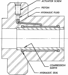
Chuck: Minimum chucking diameter 1/16”
Arbor: Minimum chucking diameter 1/4”
Maximum chucking diameters for both arbors and chucks are limited by part and tolerance variables.
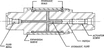
Expanding or compressing metals under hydraulic pressure is accomplished by working within the tested elastic limits of the metals being used. The general rule for expansion is .003 for the first full inch of chucking diameter and .001 for each additional inch of diameter. The following table lists typical expansion limits but these may vary somewhat due to the many variable factors for each specific application.
| Chucking Diameter | Expansion Limit |
|---|---|
| .250 | .00075 |
| .500 | .0015 |
| .750 | .0022 |
| 1.000 | .003 |
| 2.000 | .004 |
| 3.000 | .005 |
Hydraulically expanded arbors and chucks are custom engineered to embody the correct gripping force for each application. The gripping power may range from only a few pounds to several thousand pounds per square inch. They withstand rugged production operations—turning, hobbing, boring, grinding, etc., and handle the most delicate inspection operations over long periods.
Manufacturing tolerances throughout industry have been greatly reduced in recent years. In many instances conventional work holding devices are no longer capable of functioning within required production limits. In the manufacturing of precision parts the work or tool holding device must locate the part with consistent extreme accuracy so that the machine tools have the full benefit of the part tolerance. This must be accomplished without complicating the processing of machining operations whereby many non-critical part dimensions must be held to closer than necessary limits.