
Precision Devices, Inc's MicroAnalyzer 2000 is a total profiling system designed for detailed surface texture analysis.
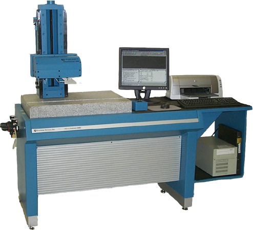
Being a computer-based system, the MicroAnalyzer 2000 is capable of meeting your current and future surface texture requirements. The system offers the high accuracy of an optical flat reference combined with the most advanced surface texture profiling software available. Our profiling software operates under Microsoft® WindowsTM, providing a system with great flexibility that is easy to use.
The system offers many unique features which are not available on other instruments:
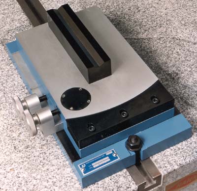
The part alignment fixture allows the part to be positioned precisely below the tracer. The part can be rotated and translated relative to the tracer without being disturbed on the top mounting plate.
 |
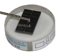 |
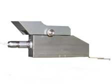
| PDT Tracer | PSM Step Master |
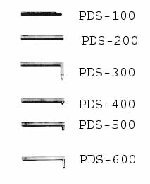
Styli above have a .0001" (..0025mm) stylus radius. The PDS-100 stylus assembly will check to within .015" (.38mm) of a shoulder. All other stylus assemblies will check within .040" (1mm) of a shoulder. |
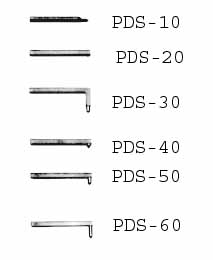
Styli above have a .0002" (..005mm) stylus radius. The PDS-10 stylus assembly will check to within .015" (.38mm) of a shoulder. All other stylus assemblies will check within .040" (1mm) of a shoulder. |
The software for the MicroAnalyzer 2000 includes a number of features for making surface texture measurements accurately, quickly, and with great flexibility.
Instrument set up consists of joystick positioning assisted by interactive on-screen feedback. Tracer centering is semi-automatic. Change tracers in the software with a mouse click; there is no need to recalibrate every time you change tracers or stylus tips. Trace speed and data spacing are fully customizable for the right balance of data collection time versus accuracy.
Data analysis is very powerful and includes a fully configurable roughness filter (2RC [ANSI], Spline Gaussian, Gaussian, Gaussian w/out end removal, Robust Spline, Rk, Rk w/out End Removal) with any standard or arbitrary cutoff. The "form" of the part (tilted line or circular crown) is removed automatically by fitting over a user-specified interval. Use the mouse to specify the interval or enter specific constraints to make the specification repeatable in the presence of differences from part to part. If you trace off one or both edges of a part, those edges can be detected fully automatically with all subsequent results restricted to the part itself.
All the profiles in the analysis (unleveled and unfiltered, leveled, waviness, roughness, etc.) can be quickly displayed, either alone or in any combination. Each can be interactively measured by positioning "measuring lines" with the mouse on-screen.
Material ratio curve (bearing area curve) analysis is comprehensive. The instrument operator can control how the curve is displayed, what portion of the roughness goes into the curve, and whether and how outlying peaks and valleys are removed from consideration. Both the ordinary roughness and the Rk-filtered roughness participate in material ratio curve and amplitude distribution function analysis.
A full range of primary roughness, primary waviness, is available. The desired parameters may be selectively enabled, simple statistics may be reported for successive measurements. Control the interval over which parameters are calculated with simple on-screen mouse movements.
Output information from the program in many ways. Print full or selected results; export profiles or parameters to the Windows clipboard to be pasted into an external document; send repeated measurement (parameter) results to a file for import into an SPC program or spreadsheet; export the raw data in an ASCII format for treatment by any external program.
When data files are saved in their ordinary format the entire reading along with all settings for instrument set up and data analysis are saved, ready to measure the same part in the same way at any later time. If desired, files may be password locked so that inexperienced operators may take new measurements but not change the data acquisition and analysis settings.
The software runs under Microsoft® WindowsTM and includes the usual WindowsTM software features: mouse and menu-driven control, icons, point-and-click dialogs, and information sharing with other applications.
To ensure that all our products are maintained to the standards you require, we offer after sales service. They include an on-site calibration/certification, field service and upgrades.
Call 734-439-2462 for details of our field services.
| Traverse Length: | 64 mm (2.5") and 114 mm (4.5") maximum |
| Reference: | Optical flat |
| Leveling: | Semi-automatic software leveling |
| Stylus Tip: | Diamond with 90° included angle Conical shape with a radius of 2.5 µm (0.0001") (standard), 5 µm (0.0002") and 10 µm (0.0004") (optional) |
| Transducer: | LVDT with a dynamic range of 0.5 mm (0.020") (standard) or 1 mm (0.040") (optional) |
| Operation: | Skidless |
| Filters: | Standard 2RC, Phase-Correct 2RC, Gaussian, Rk Filter or No Filter; User selectable or standard cutoff length |
| Roughness: | Ra, Rt, Rp, Rv, Rtm (RzDIN), Rpm, Rvm, Rti(1-5), Rz(1-5), tp, Rq, Rsk, Rku, R3zISO, PC, Sm, Rk, Rpk, Rvk, RzISO, Mr1, Mr2, Rpk*, Rvk*, Vo, Rqp, Rqv, Mr2c, a, Λq, Δa, Δq |
| Waviness: | Wa, Wt, Wp, Wv |
| Texture: | Pt, Pp, Pv |
| Form: | Straightness, Slope, Radius |
| Printer/Plotter: | HP LaserJet or equivalent |